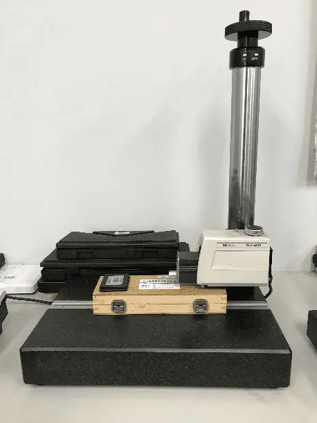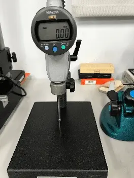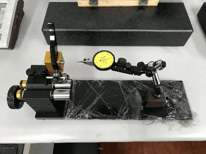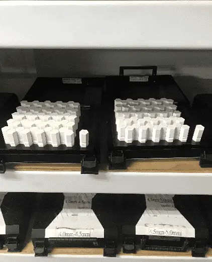
Product Quality Comes from Design-manufacturing, Not from Inspection.
Neither sampling inspection nor full inspecton can help with quality improvement, modern quality management has regarded process design and continuous improvement as key capability of a supplier. TC specialty corp. is devoted to helping the factories to find out the best resolution for customer’s requests for products.
We offer you:
- PPAP & IMDS submission
- Process design and development
- SQE for supplier improvement
- Patrol inspection & final inspection
How to Use PDCA Cycle to Improve Process Design
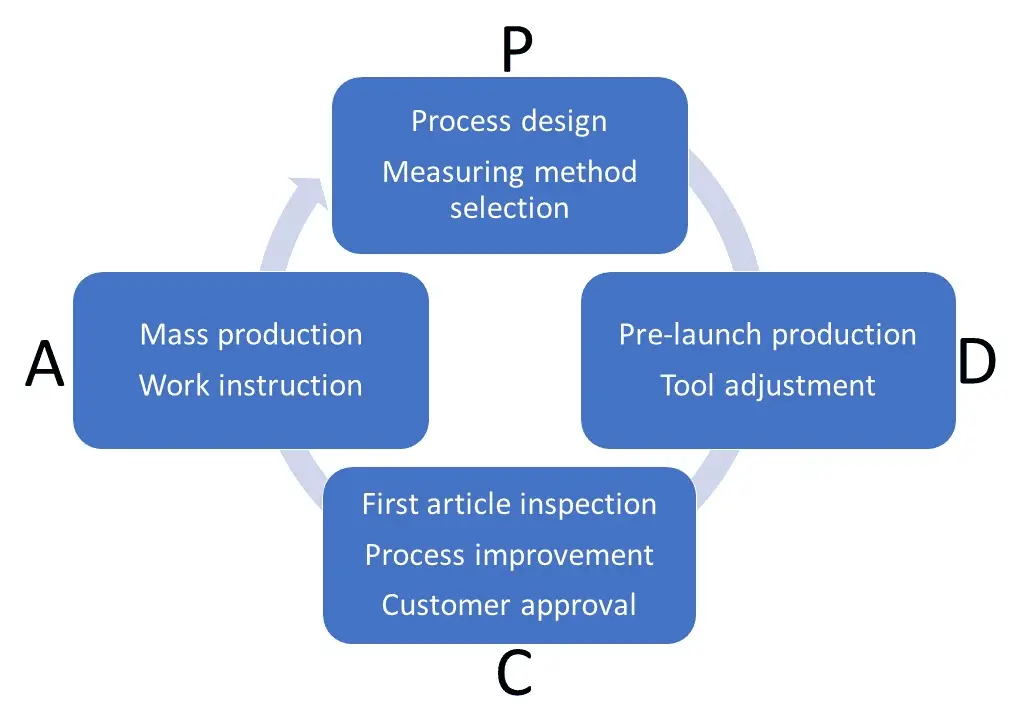
In 1950, Dr. Deming proposed a PDCA cycle in Japan. It’s a four-step management method used in business for the control and continuous improvement of processes and products. For decades this cycle is widely applied for improving products, people and services.
In TC Specialty Fasteners Corp., we use PDCA cycle to check our manufacturing process. Below is our PDCA cycle
- Plan – Before getting into real production, we do feasibility discussion with our supplier, that includes the material used, process design and measuring method and then have a process plan completed. If the customer needs PPAP submission, we submit PPAP documents with specific level that customer requests.
- Do – According the pre-launch process plan, we produce a small amount of product sample to verify our process design.
- Check – The first article inspetion is necessary to verify that the process is good for part production. If the part quality is not good enough, SQE takes part in the the process improvement and redo the step a, b and c until no quality issue is found.
-
Act – After the Plan-Do-Check procedure, we ensure any problem in the process is revised, and then have work instruction completed for the mass production to make sure every steps is compliant with the process design and good products can be manufactured.
Inspection Procedure
- Receiving inspection
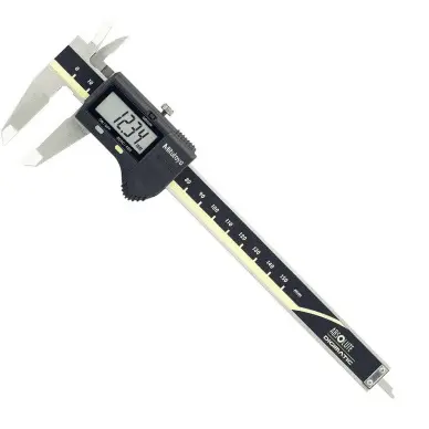
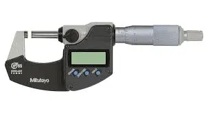
Using a wrong material in manufacuring process will lead to severe consquence, wrong physical and chemical properties probably result in safety issue, that’s why receiving inspection is important. When a lot of material is delivered to the qualified factory’s warehouse, we check the material certificate as well as the dimension with caliper or micrometer. Labeling on the material is also important after receiving inspection, correct labeling prevents the operator from miss-taking or material mixing. - Patrol inspection and inspection in process
We select factories which carry out inspecton in process every 2-3 hour. When defect is found in process, manufacturing be stopped and all the parts since last inspection have to be checked to ensure all defective parts are discarded.
Beyond the inspection in process from supplier, TC specialty corp. is also playing a role as a supervisor, we implement 5-20 pieces of sampling inspection during part production. - Final inspection
Although sampling inspecton can’t improve any proccess or products, final inspection is still necessary for outgoing parts. We do the final inspection according to AQL 0.65, level II.
Knowledge
How to Measure the Geometric Tolerance?
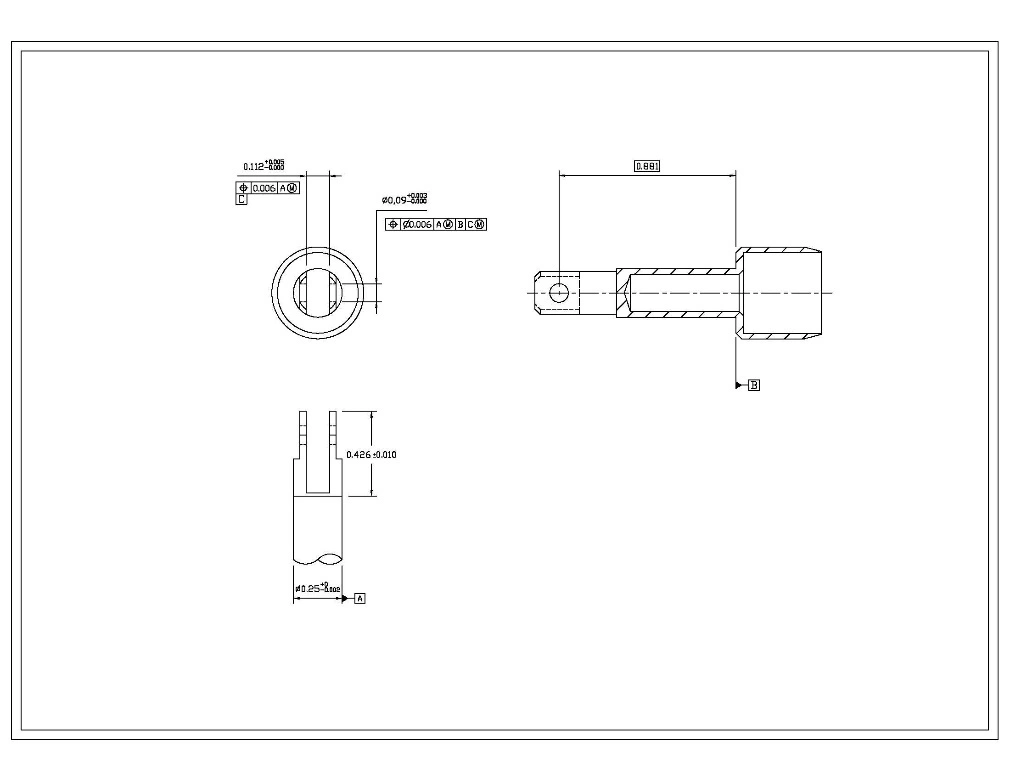
According to the engineering diagram, we have to check out the position of the hole with diameter 0.09 inch(the toleranced feature) relative to the datum A, B and C.
Before we start the inspection, it is necessary to analysis what the purpose the geometry requirement is? What does it really mean when we define the position of diameter 0.09 by referring to the three datums: the virtual axis A, the plane B and the virtual plane C?
In this case, we try to understand the geometric tolerance in easier way. The hole we concern must be accurately located in a 3D space, to do this, we need to build a 3D reference system, say x, y, z coordinate. Usually we use the workpiece itself as the 3D reference system, so we can define the virtual A axis as z axis and the datum B plane as x-y plane. In this way, we already build a Cartesian system.
As we know, a particle in a Cartesian system has six freedoms, which includes moving along x, y, z direction and rotating around x, y, z direction.
Now let’s see how it works. As to the datum B, the key feature diameter 0.09 inch should be located on a plane(for convenient reason, we called this plane as X plane) which is apart from the B plane(the x-y plane) with an ideal distance 0.881 inch. After do that, the key diameter’s movement is now restricted. It can only rotate and move on the X plane, meaning that three freedoms left on the toleranced feature.
1st freedom: rotation on the X plane;
2nd freedom: movement on x direction ;
3rd freedom: movement on y direction.
For the purpose of locating the toleranced feature, we need to give more restrictions on the toleranced feature until no freedom can be found. In other word, the three freedom must be removed from the workpiece.
Datum A is the virtual axis derived from the outside diameter 0.25 inch. Application of datum A enforces the toleranced feature to only rotate around the virtual axis, and no longer move freely on the X plane.
Now we got a toleranced feature with only one freedom rotating on the X plane and around the Datum A.
In the last step, we need to use the Datum C to locate the toleranced feature precisely and no freedom can be found on the toleranced feature.
Datum C is a virtual median plane derived from the gap with width 0.112 inch. This virtual plane limits the direction of the rotating toleranced feature, the diameter 0.09 inch hole, to only be perpendicular to datum c itself.
Now we can see that after the location implementation of three datum A, B and C on toleranced feature, the toleranced feature is located precisely in the 3D space and no freedoms in Cartesian coordinate can be found.
After the analysis above, it comes to conclusion that to locate the hole we concern precisely, we need to identify that the hole is parallel to the plane B with a distance 0.881 inch, getting through the axis A and perpendicular to the virtual plane C. Keeping the analysis in mind, it’s easier to realize what to measure and how to test when geometrical tolerance is requested on a drawing.

